New High Contrast Coronagraphic Locations For STIS Provide Inner Working Angles Of ≥ 0.2"
András Gáspár, Steward Observatory, The University of Arizona, agaspar@as.arizona.edu,
Glenn Schneider, Steward Observatory, The University of Arizona, gschneid@email.arizona.edu,
Initial results are reported on the calibration proposal GO 12923, intended to test the performance of the previously untested and not commissioned BAR5 ("the finger") occulter of STIS, originally designed to enable inner working angles at just ≈ 3 λ/D (half of the currently supported narrowest occulting aperture WEDGEA0.6). Additionally, the corners of the BAR10 occulting element were also tested for small IWA coronagraphy. In this report, apart from the initial raw and also final combined images of the observations, contrast levels achieved in the program are also shown and recommendations are made for future observations and the settings to use in APT.
Table Of ContentsI. Introduction
II. Program Summary
a. Observation Summary
b. Pointing Precision and Limitations
c. Contrast Levels
III. A Cookbook For The New Modes
a. POS-TARGs for BAR10 positions
b. POS-TARGs for BAR5 positions
c. APT Options/Keywords
d. ETC Calculation Cookbook
IV. Appendix
I. Introduction
In Cycle 20, program GO12923 was carried out with the goal of calibrating the previously untested BAR5 occulter ("the finger") of STIS (Figure 1), originally designed to achieve inner working angles (IWA) of ≤ 0.2" (i.e. 2 AU at 10 pc). The occulter was referred to as BAR5 pre-launch (Clampin et al., 1997 ISR-95-08), however, after being bent it was humorously referred to as "the finger". Here, to follow heritage naming, the original naming of the aperture "BAR5" is used (which indicates the occulter's length and not width.) Such small IWAs with high contrast can help answer of some of the most compelling questions in astrophysics today. Observations enabled by this new coronagraphic capability will advance exoplanetary science by revealing the inner regions of circumstellar protoplanetary and debris disks, and detect and resolve close orbit substellar companions to nearby stars. Extragalactic studies of host galaxies of bright QSOs, damped Lyman α absorbers, and feedback mechanisms in the bulges of AGN can be pursued at distances closer to their hosts than ever before. HST has flown five (and operated three) coronagraphs. STIS is the last visible space coronagraph currently used, providing a unique observing mode. The coronagraphic mask (50CORON) of STIS has two perpendicular wedges, on which eleven specific locations are specified as coronagraphic locations, with the widest position providing a theoretical 1.4" and the narrowest providing a theoretical 0.3" IWA. Apart from these, there is a wide BAR10 occulter (see Figure 1) and a very narrow BAR5 occulter (the finger), providing a theoretical IWA of 0.15". See the STIS documentation for further information (http://www.stsci.edu/hst/stis/documents/isrs/199508.pdf). During the program, dithered positions at the BAR5 occulter were tested and ones near the corners of the BAR10 occulter (Figure 2). All together 4 stars were observed (2 targets and 2 references) at these three test positions. In this STAN report, a brief summary of the program is given and the observational results, with regards to the best positioning on the apertures as well as the achievable raw contrasts.
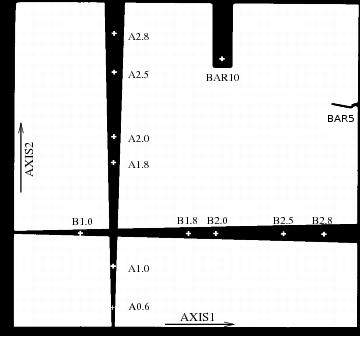
Figure 1: Flat field image with coronagraphic apertures marked.
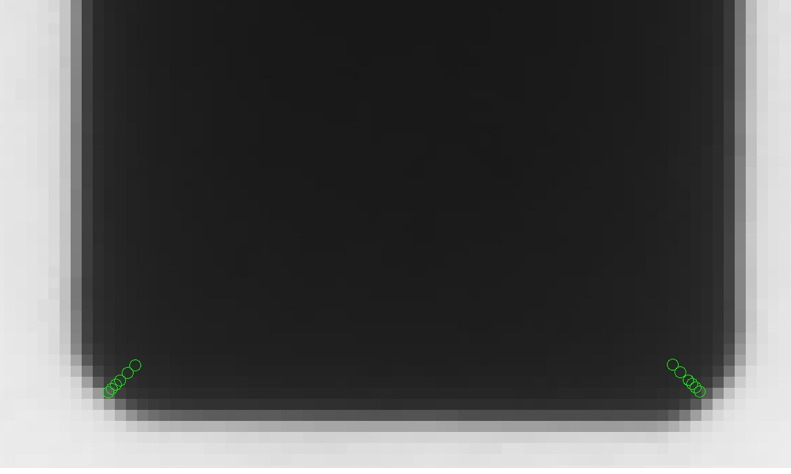
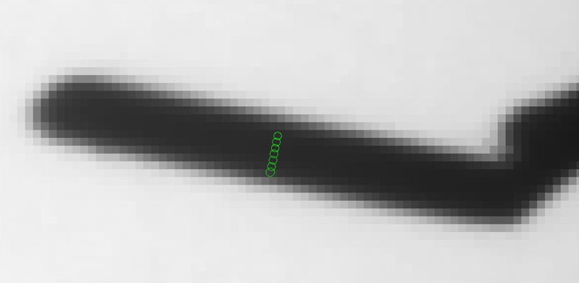
Figure 2: Flat field image with originally planned coronagraphic apertures marked. Note: these positions were revised for our second set of observations.
II. Program Summary
a. Observation Summary
The BAR5 occulter was unfortunately bent on the ground during assembly. Although flat field images taken over the past two decades have shown it to be astrometrically stable in the field, its usefulness as an occulter was never tested, even though its width at 0.3" can theoretically enable inner working angles at half of the current smallest one provided by WEDGEA0.6. A default pointing position currently exists for the BAR10 occulter ("+" in Figure 1), but does not for BAR5, so the dithered pointing offsets used for the BAR5 occulter are referenced from the default BAR10 position.
Two target sources: AU Mic and β Pic were observed, both with color matched PSFs. These targets were chosen to span the domain of most star color indices, from very red (AU Mic, B-V = +1.44 at spec M0; PSF: HD191849, B-V=1.453) to nearly spectrally neutral (β Pic, B-V = 0.17 at spec A6; PSF: δ Dor, B-V=0.21) since coronagraphic performance is source-color dependent under the very broad STIS bandpass. Each target-PSF pair was observed in 3 orbits, with two target observations, offset by 33 degrees, and the PSF observation, back-to-back. Following the initial acquisition of the AU Mic dataset, the target positionings for the β Pic observations were refined.
Altogether, 15 dithered positions were planned for the AU Mic and 19 for the β Pic observations, with the additional positions allowed at β Pic due to the slightly shorter exposure times. Due to the initial uncertainties in the POS-TARG placement of the sourcer and in the sharpness of the occulter mask edges, larger dithers were made for the AU Mic (and its reference source) than for the β Pic (and its reference source) observations, which were refined following the initial analysis of the AU Mic dataset.
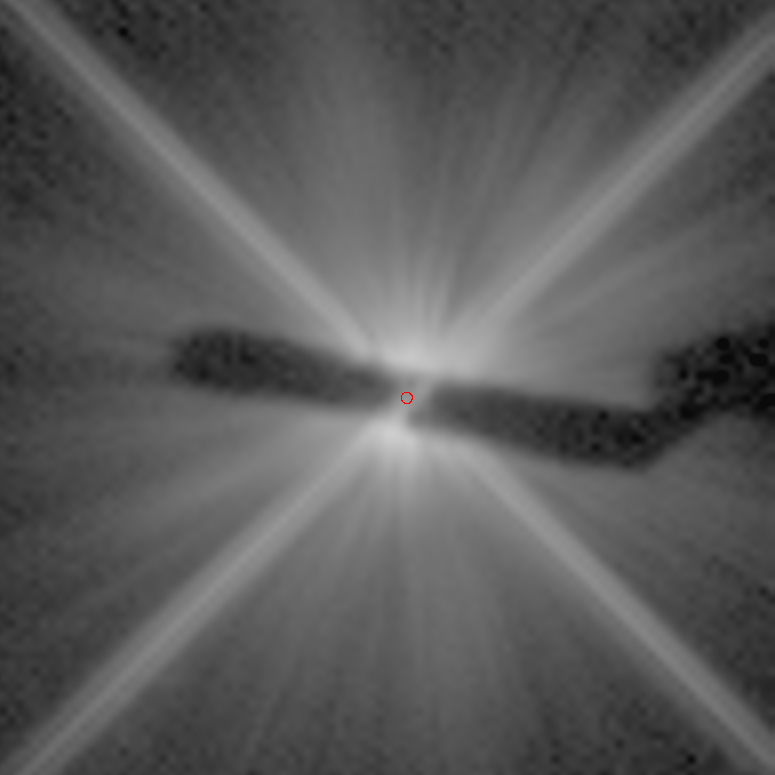
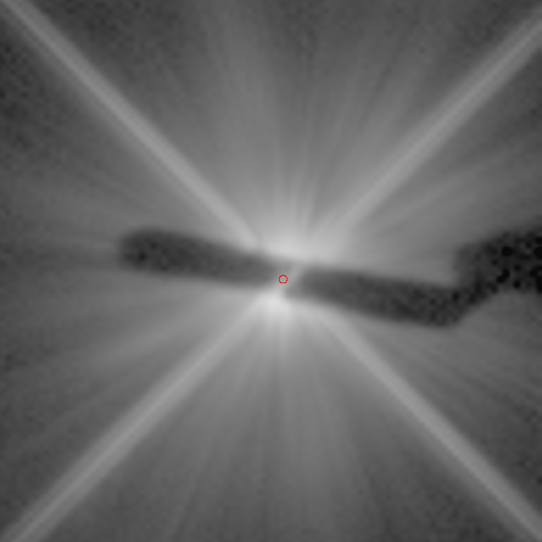
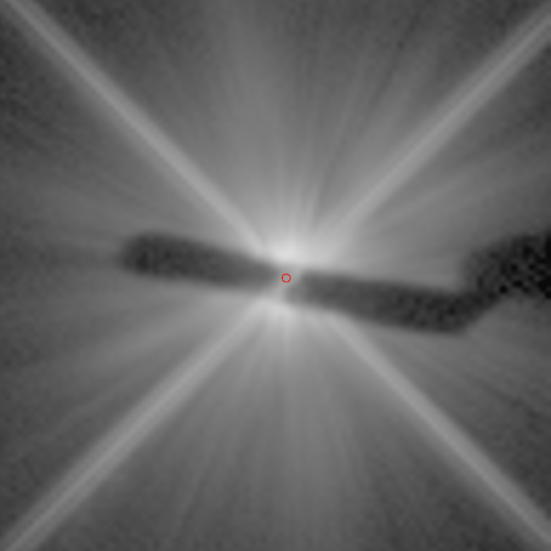
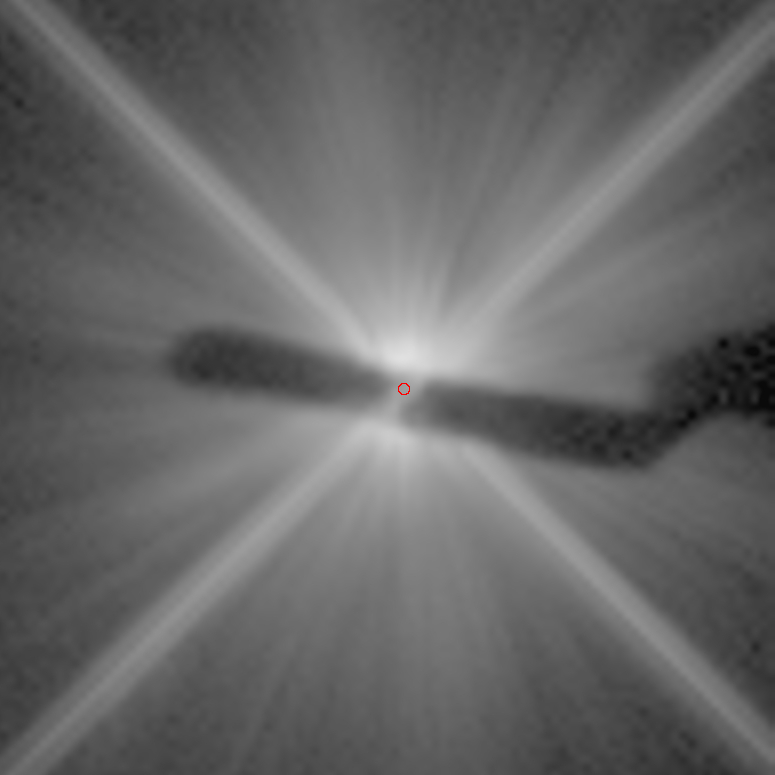
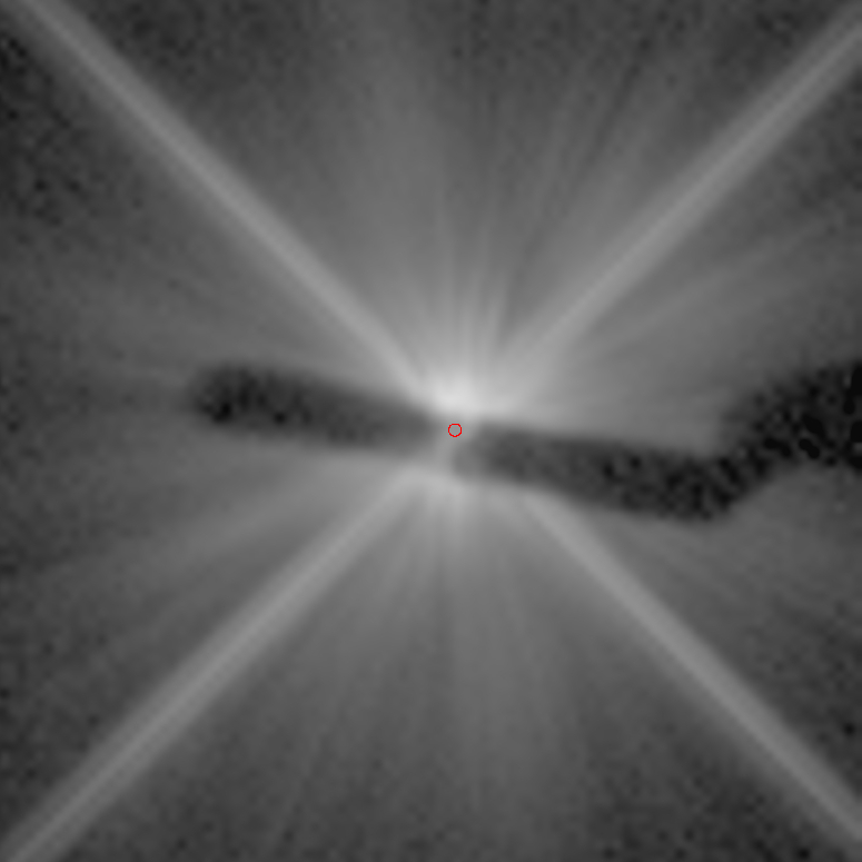
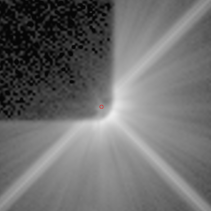
In Figure 3, preliminary images of β Pictoris are shown. The images are constructed from the median combination of the data taken at all dither points, following position matched PSF subtraction and conservative masking of each PSF subtracted image of all saturated or unsampled (occulted) pixels. An inner working angle of ~0.24" is achieved, however, with further image analysis, it may be possible to decrease it to the occulter's nominal IWA of 0.15". Based on an apriori determination of the orbit of β Pic b, the position of the planet (red circle) is shown for the epoch of the observation - significanly beyond the IWA acheived - in the enlarged image in the right panel. The goal of the calibration proposal was to fine tune the BAR5 and the corners of the BAR10 elements as occulters. With the behavior of the instrumental system known, deeper observations can now be taken, yielding significantly higher S/N images.
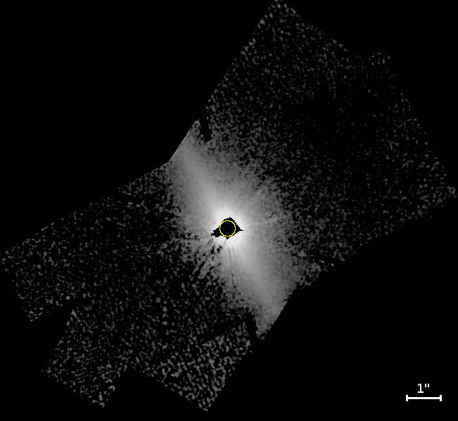
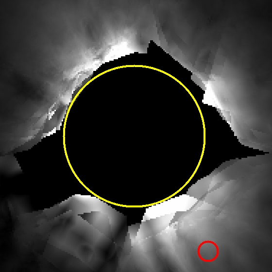
Figure 3: Left panel: The PSF subtracted, masked, and combined image of β Pic; Right panel: The location of β Pic b in the image; the deviations in the central region where only a few images were combined due to masking are on the orfer of 10%. North is to the TOP of the image and East is to the right. In both panels, the yellow circle has a stellocentric radius of r = 0.24".
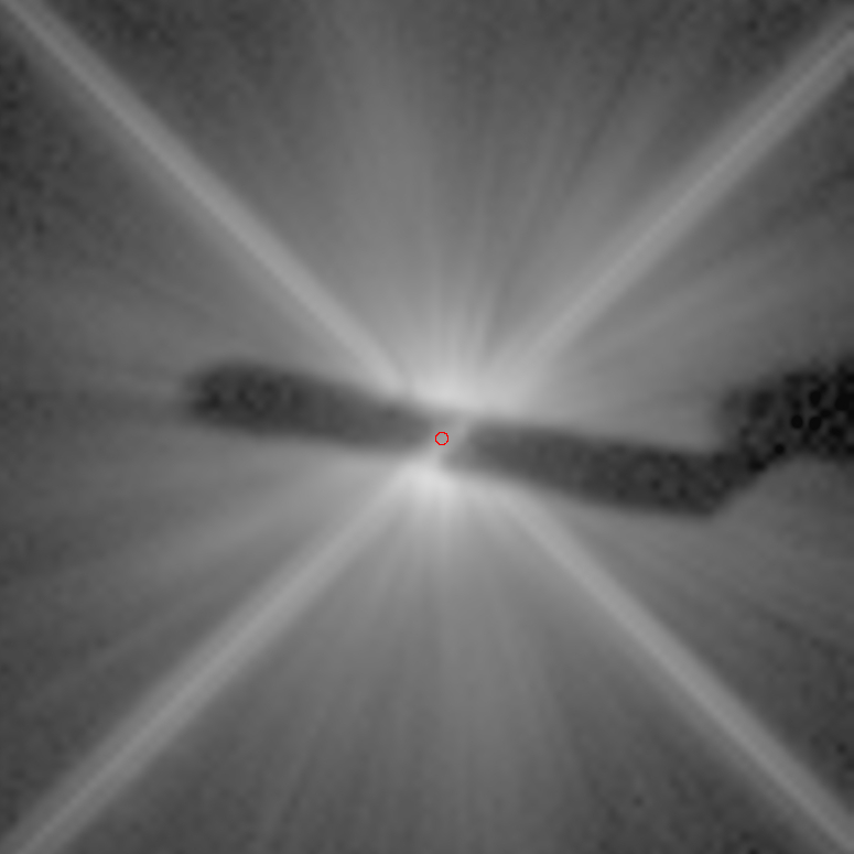
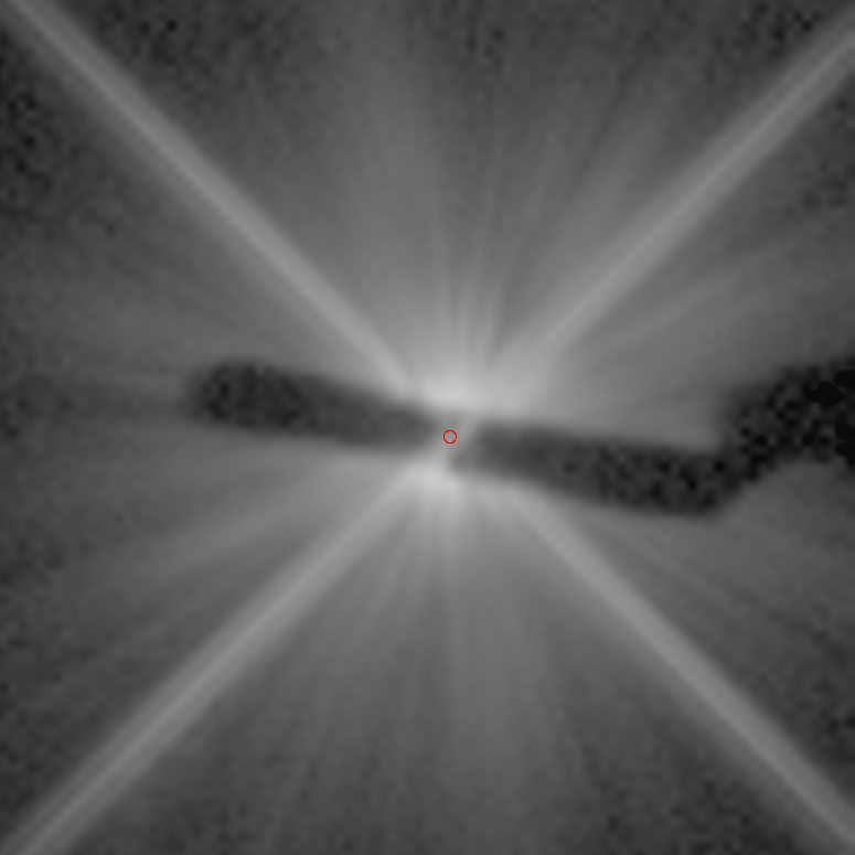
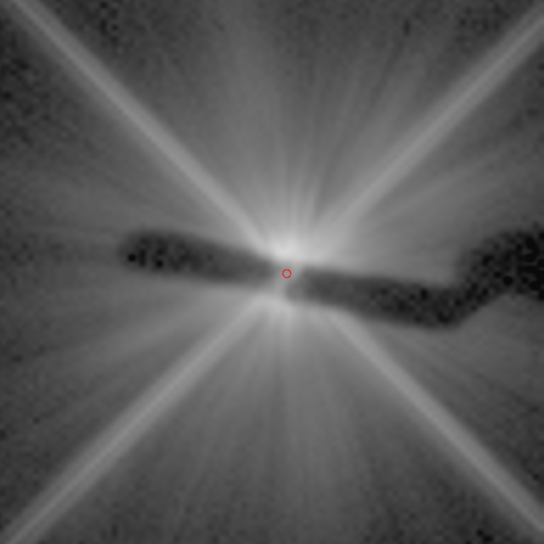
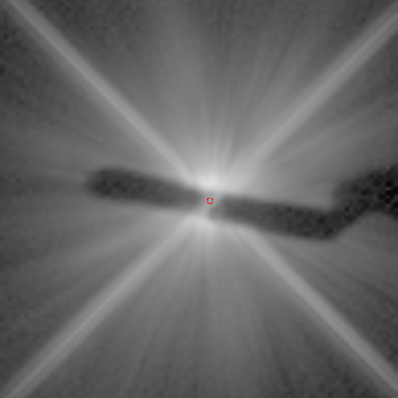
Finally, in Figure 4, a comparison is shown between the IWA achieved in GO12228 (left panel) and the calibration program GO12923 (right panel) at AU Mic. The images are at the same spatial and flux scale. The GO12923 image is from only a preliminary data analysis and can be further improved on.
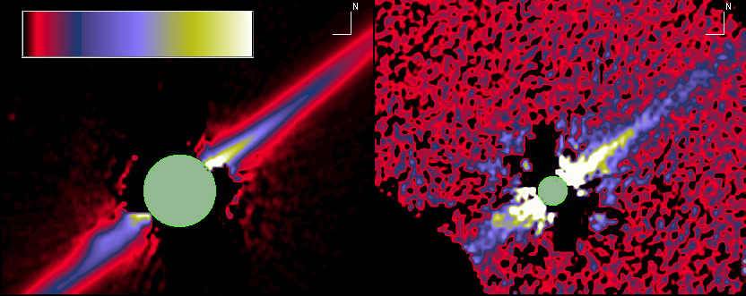
Figure 4: Comparing the AU Mic observations of the GO12228 program (left panel - 12 ksec total integration time) with that obtained in GO12923 (right panel - 23 seconds total integration time). The images are on the same image flux and spatial scale, orientation, and linear display dynamic range: 0 to + 15 counts/sec per pixel.
The 1 σ "pointing precision" of the AU Mic observations relative to the planned
offsets from the BAR10 aperture fiducial is summarized in Table 1. They are consistent with the 1/4 px
mask redeployment precision of STIS.
For both the BAR10 LL and LR corners, the stellar PSF core disappears between "radial" scan
step planned positions of +0.20" and +0.25" from the as defined rounded edge of the corner (see image stamps in the Appendix).
The edges of the mask are not geometrically sharp, in part because the mask plane is not perfectly conjugated to the reimaged
focal plane (i.e. slightly afocal on the detector), and also due to diffraction and scattering effects.
| Position precision | <σ>x | <σ>y | <σ>tot |
| BAR5 | 0.0577 | 0.261 | 0.267 |
| BAR10 Lower Left corner | 0.069 | 0.191 | 0.203 |
| BAR10 Lower Right corner | 0.087 | 0.267 | 0.281 |
c. Contrast Levels
In Figure 5, the RAW contrast levels of δ Dor is shown
(GO12923raw.dat), which was the PSF template for the
β Pic observations. "Contrast" here specifically means
the flux density of the emission measured at any location (within a resolution element)
divided by the flux density within the central resolution element of stellar PSF core,
if it were unsupressed by coronagraphy and/or PSF-subtraction.
In this report, contrast is directly and expediently measured per pixel, rather than per
resolution element (as the two are identical to ≈ 20% with the STIS 50CCD PSF),
with the central pixel in the STIS PSF enclosing 23% of the total stellar energy.
The curve shows that the coronagraph behaves well in the new IWA regime.
The contrast curve matches up quite well with the PSF subtracted one of a G2 V=7 mag
source within the GO12228 program (GO1228psfsub.dat), also shown in Figure 5.
The AU Mic observations shown above also support the statement that the contrast limits for the two datasets match closely.
With RAW coronagraphy, we achieve 9.37 magnitude increase in contrast at 0.5" and 11.27
magnitude at 1.0" radial distance from the occulted source per resolution element (pixel at STIS).
To zeroth order, the expected contrast performance can be estimated by calculating the
background limited S/N of a target source relative to the GO12923 raw contrast curve. This
approximation fails close to the source, where systematic residuals dominate photon statistics.
This can be improved on, however, with observations performed at multiple spacecraft orientations,
which is also recommended (see below) for multiple other reasons.
Further info comparing various STIS contrast levels can be found at
http://www.stsci.edu/hst/HST_overview/documents/calworkshop/workshop2002/CW2002_Papers/grady.pdf
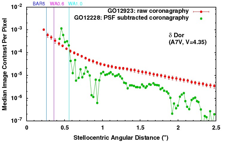
Figure 5: RAW coronagraphic contrast levels achieved at the BAR5 occulter in the GO12923 program (GO12923raw.dat) and PSF template subtracted coronagraphy at the WEDGEA0.6 aperture in the GO122228 program (GO1228psfsub.dat). Vertical lines show the inner working angle distance plus one resolution element (to account for edge effects) for STIS occulting positions. Contrast level errors are median absolute deviations for the GO12923 data.
III. A Cookbook for the new modes
The calibration program showed that sources can be placed at these new apertures and
that this can be repeated with high precision. It also showed that dithering is necessary for high
precision PSF subtraction and object placement, as the mask redeployment carries with itself a 1/4
pixel uncertainty, the differential effects of which can be largely mitigated at small IWA with
position-matched PSF-subtracted coronagraphy. It is highly recommended that PSF template stars are
observed together with the target objects, in back-to-back observations when utilizing the BAR5
occulter (or the BAR10 corners), as it provides an improvement in contrast of 4 magnitudes and a
photometrically conservative procedure.
The PSF source needs to be color (spectral-type) matched to the target source, and be relatively
close to the target on-sky (within a few degrees). The target and PSF reference sources should be
observed with exposure times that yield similar total counts (and not count rates). Due to CTE degradation
(http://www.stsci.edu/hst/cos/documents/newsletters/cos_stis_newsletters/full_stories/2013_06/CCD_linearity),
it is not recommended to use a target-PSF pair that differs in total flux by more than a factor of 5-10.
It is also recommended imaging the target at multiple orientations, beyond
the two rolls utilized in the calibration proposal. Use of the BAR5 (as demonstrated), allows probing
closer to the star, but multiple rolls not only allow more complete spatial coverage (to sample "around" the
occulter and diffraction spikes), but also in analysis to decorrealte quasi-static PSF-subtraction residuals
that are invarient in the detector frame as the spacecraft is rolled. The PSF source, obviously, only requires
a single orientation.
a. APT Options/Keywords
Target orientation: To align an extended object along the AXIS2 (Y axis - column of the CCD, see Figure 11.1 of the STIS Instrument Handbook), an orientation angle of PA+45 (or PA+225) is necessary. For most efficacious PSF subtraction, multiple contiguous orbits (visits) at DIFFERENT field ORIENTation angles, within the allowable roll range constraints are advantageous and recommended with a MINIMUM of two different roll angles, although more provide significant advantages in removing PSF subtraction residuals. The roll (orientation) differences should tile the roll angle space for target region of interest between the HST diffraction spikes to the largest degree of angular separation possible between the spikes and target region of prime interest in multiple visits. E.g., the nominal orientations for a two-orientation observation of PA+45+/-22.5 deg (+180 works as well for "symmetric" objects).
Guide Star Acquisition: Pointing and roll control with 2-FGS guiding.
Guiding Tolerance: 0.005" for coronagraphy
Config: STIS/CCD
Mode: ACCUM
Spectral element: Mirror
Polarizer: none
Aperture: BAR10
Optional parmeters:
- CR-SPLIT at least of 5 (max of 8), to build SNR
- SIZEAXIS2 large enough to include extended object. Smaller images read out enable multiple exposures.
- CENTERAXIS2 (available but not supported mode) = center of object (820 for BAR10 corner and 700 for BAR5 center)
Target Position Requirements: the recommended POSTARG values are given in Table 2 and described in detail in the following subsections.
| Position | Dither- | Center | Dither+ |
| BAR5 | 17.48331, -7.43398 | 17.48579, -7.42153 | 17.48827, -7.40908 |
| BAR10 Lower Left corner | -1.24168, -1.31433 | -1.23270, -1.30535 | -1.22372, -1.29637 |
| BAR10 Lower Right corner | 1.34703, -1.30914 | 1.33805, -1.30016 | 1.32907, -1.29118 |
b. POS-TARGs for BAR10 positions
The location of the BAR10 aperture is not exactly centered on the occulter, which is why the POSTARG arguments of the Left and Right corners are not symmetric. It is found that for these corners a minimum offset of 0.225" is necessary as the mask edge itself is not geometrically sharp (see postage stamp images of observations in the appendix). For the Left corner a POSTARG of -1.23270 -1.30535 will place the source at 0.225" from the corner. For the Right corner a POSTARG of 1.33805 -1.30016 is necessary. A dithering of a 1/4 pixel (0.0127") along the 45 degree apex is recommended for targets and PSF sources.
c. POS-TARGs for BAR5 position
The necessary POSTARG to place the sources behind the BAR5 (Finger) occulter is 17.48579 -7.42153 from the BAR10 aperture. The BAR5 is positioned at 11.28 deg CW from image +Y. Dithering the target and the PSF by 0.0127" along the perpendicular is recommended, to POSTARG-: 17.48331, -7.43398, POSTARG+: 17.48827, -7.40908.
d. ETC Calculation Cookbook
Target Acquisition, and exposures: Each target is recommended to be acquired with mode-2 target acquisition with SNR>~100 in the central pixel (a ND filter may be needed, see STIS ETC). High SNR is recommended for TA as the images are also used as pre mode-2 astrometric anchors in assessing the "behind the occulter" target position to high precision. The detectors should reach 90% of full-well depth during the exposures, with the target coronagraphically occulted, at the edge of the aperture, 0.15" from the star, at the nearest positioning. For this program, using the ETC, this was scaled from observations predicated upon that an A0 star with V=3.55 reaches 90% full-well from the PSF halo in 1 second, based upon previous STIS coronagraphic observations allowing for up to as much of 1/2 pixel of possible target decentering in acquisition performance. To allow for cosmic ray rejection, to reduce inter-image phase-asynchronous video pattern noise, and to improve photon SNR, 5 CR-SPLITS were taken at each position of the first target, AU Mic, and 6 CR-SPLITS at each position of the second target, Beta Pic. A maximum of 8 CR-SPLITS is allowed.
IV. Appendix
Scans were constructed across the BAR10 corners and the BAR5 occulter ("the finger") relative to the BAR10 fiducial position, which is defined in the SIAF file. This required de-constructing the BAR10 fiducial position w.r.t. the latest available flat field image, using the flat field image and the latest available coronagraphic image taken at the BAR10 location, which happened to be of Fomalhaut (OB7914010 and OB7915010). The bright PSF halo of Fomalhaut back-lit the BAR10 and BAR5 apertures, while the diffraction spikes from the star enabled locating the precise position of the BAR10 aperture w.r.t. the coronagraphic mask. Positions were planned at various distances from the corners of the BAR10 occulter along a 45 degree apex. The line angle of the finger is measured at 11.28 deg CW from image +Y. Imaging positions were placed at various distances from this central point, along a perpendicular to the central line.
Following the execution of the first set of observations of AU Mic and its respective
PSF star, the POSTARG arguments for the second set of observations of Beta Pic and its
PSF were refined. This involved correcting for a shift in Y at the BAR5 occulter, due to geometric distortions.
Dithering was also performed with smaller steps around the now well defined POSTARG location of the central line of
BAR5. The AU Mic data also showed that the initial offset of 0.15" from the BAR10 corner was insufficient,
so it was increased as well. It is also emphasized that the CENTERAXIS2 parameter includes the 20 pixel
overscan region, which was not included in the first set of observations.
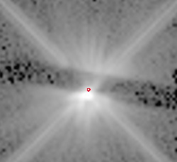
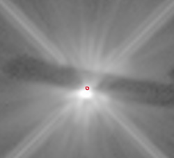
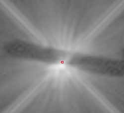
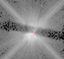
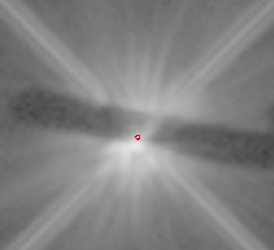
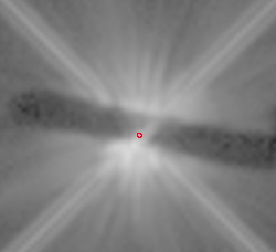
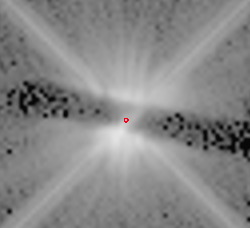
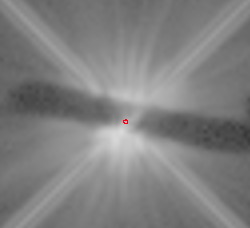
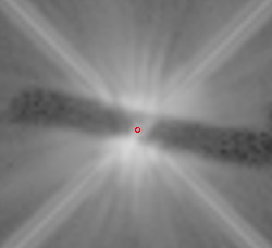
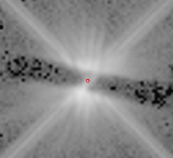
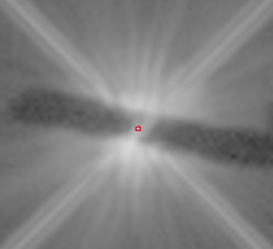
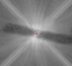
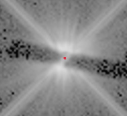
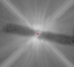
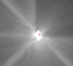
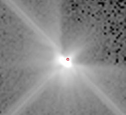
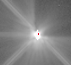
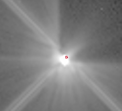
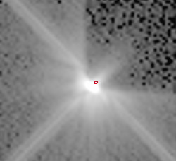
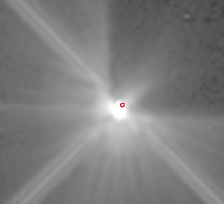
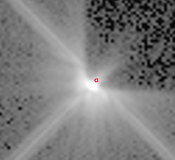
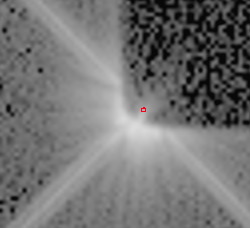
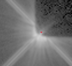
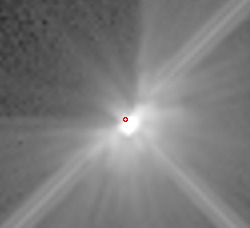
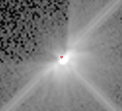
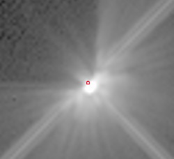
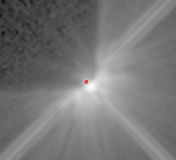
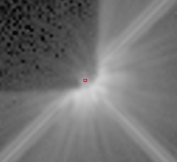
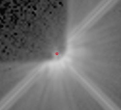
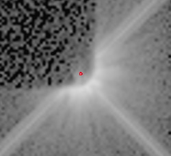
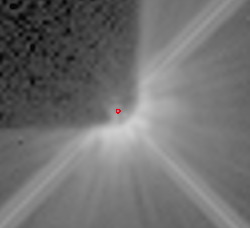
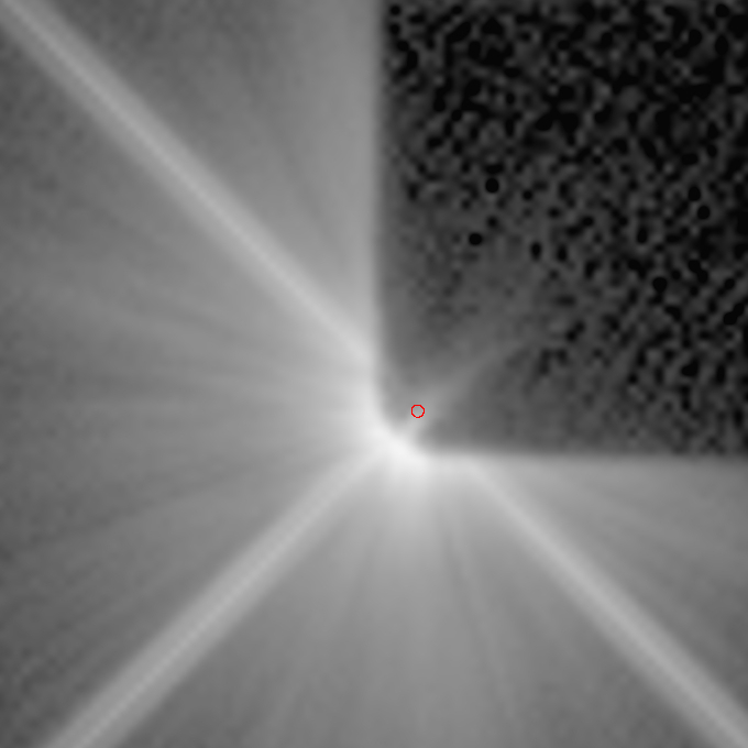
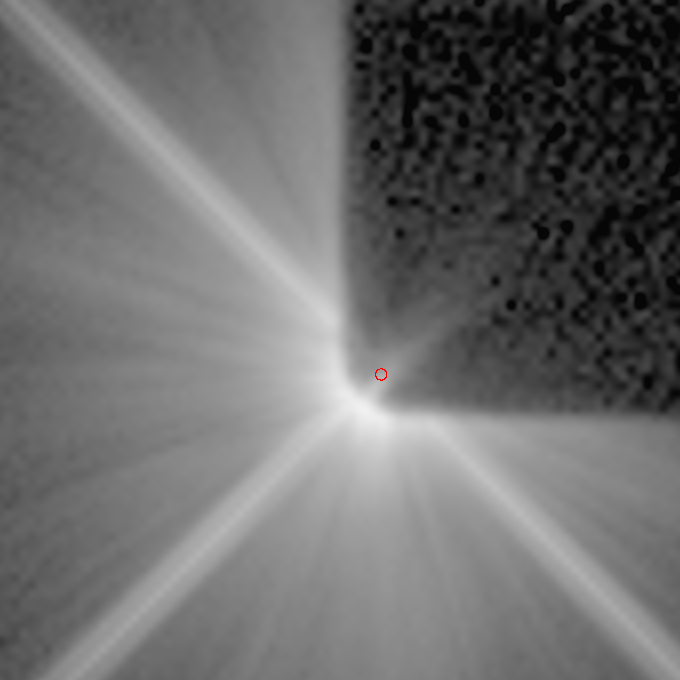
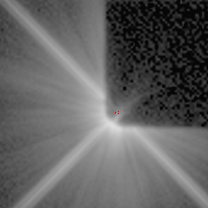
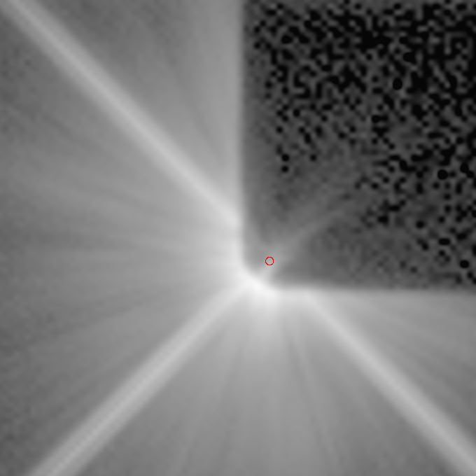
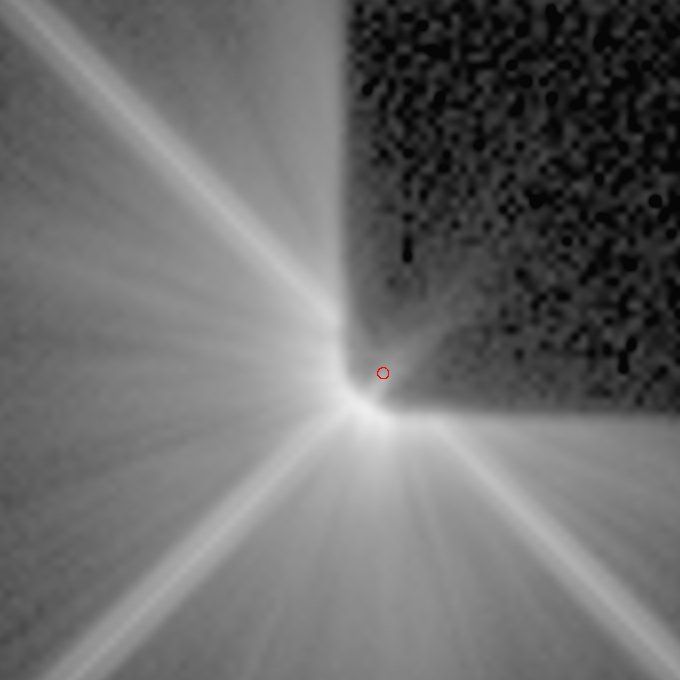
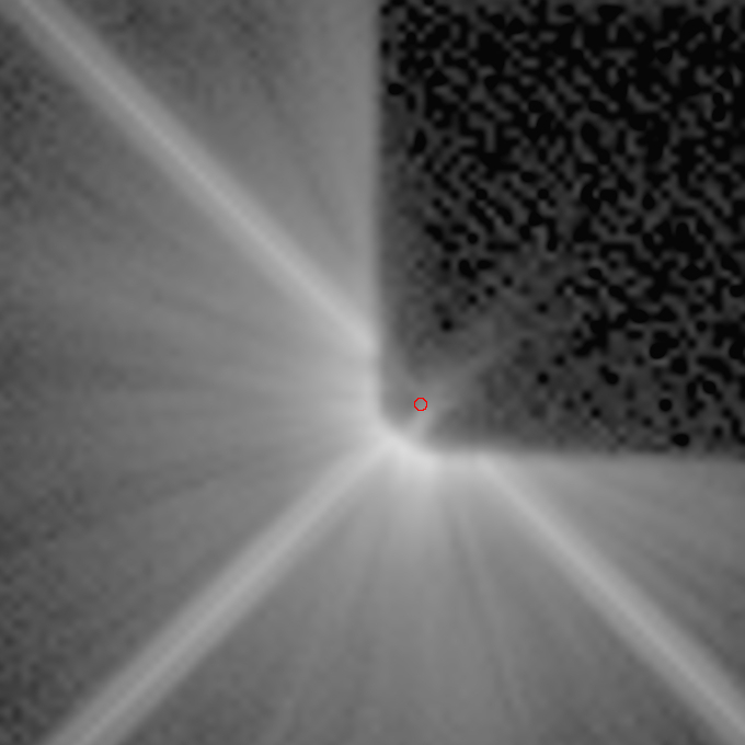
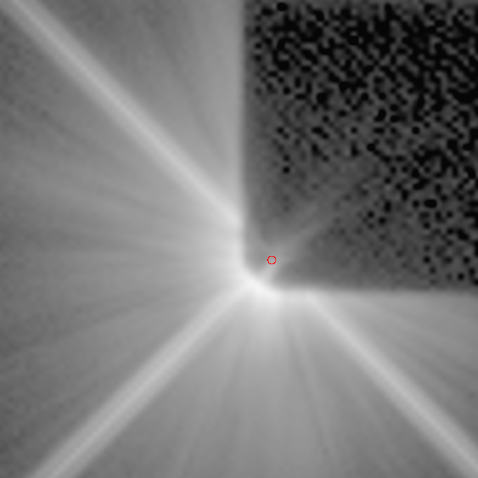
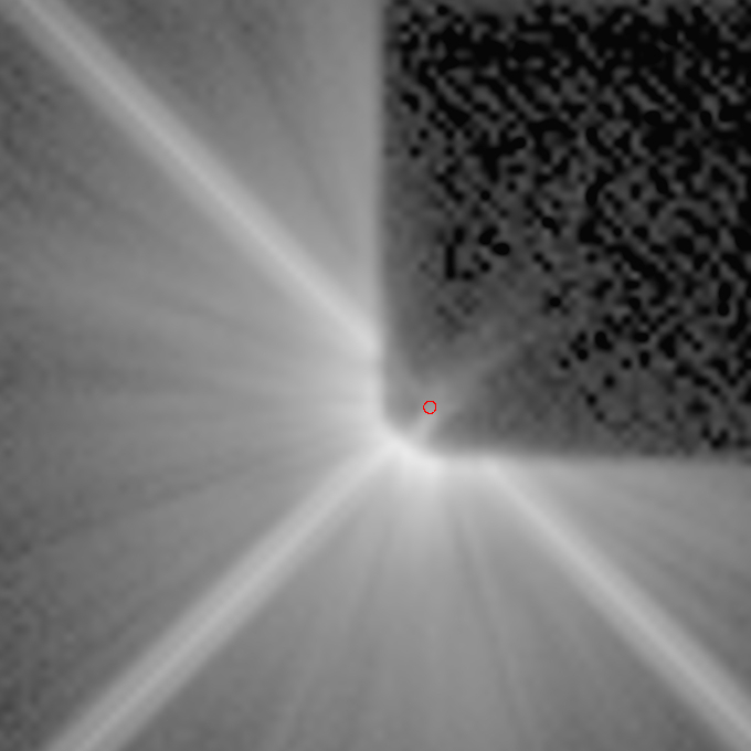
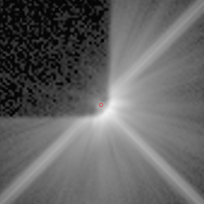
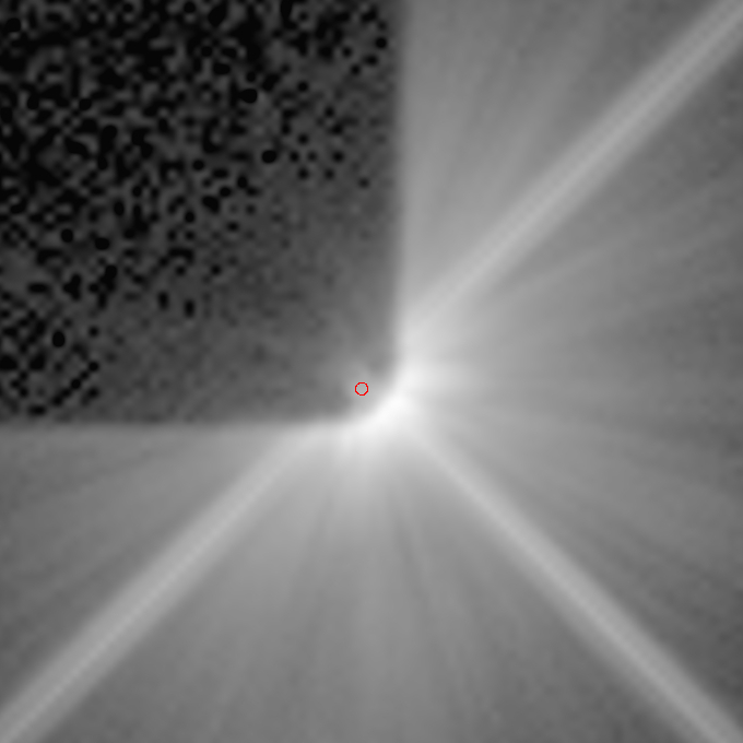
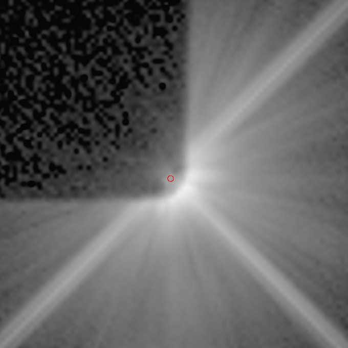
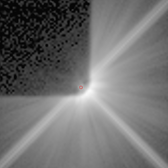
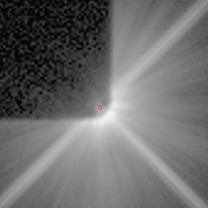
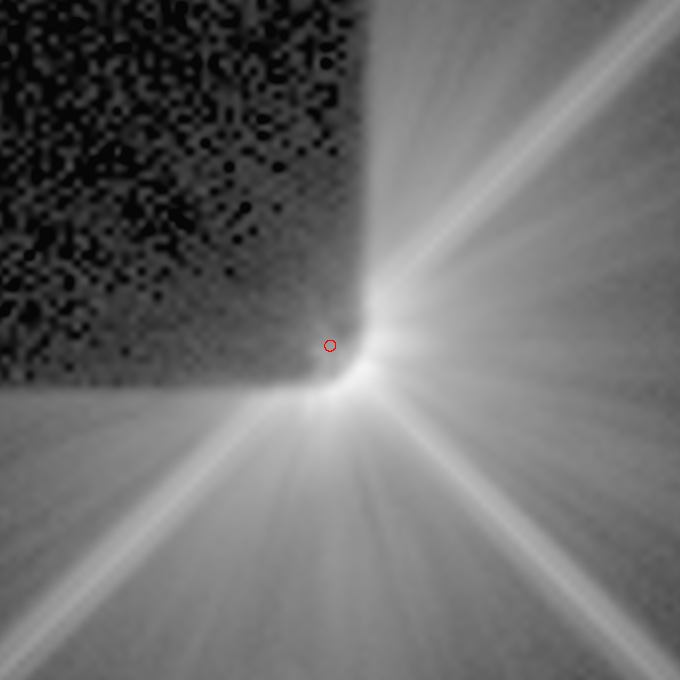
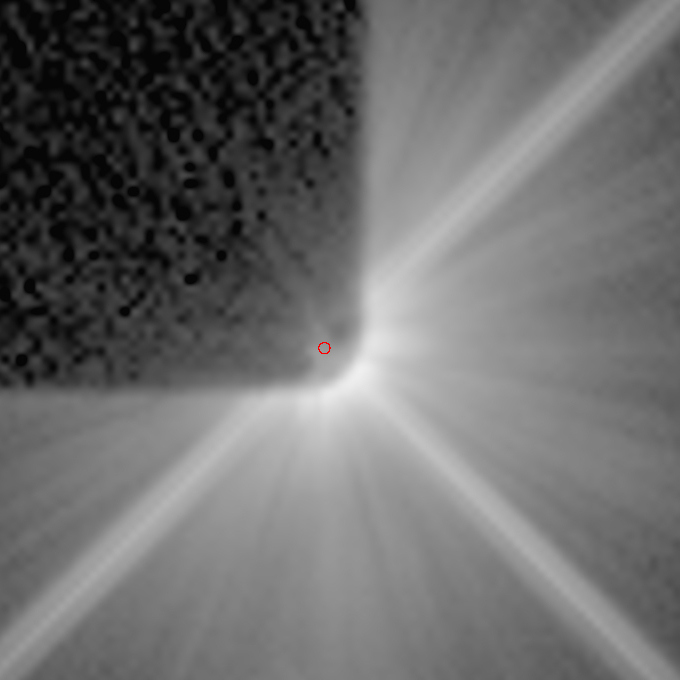
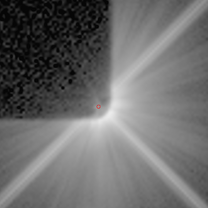
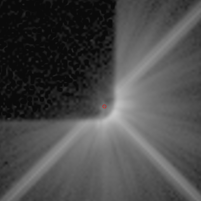
Below, the postage stamp cutouts of each observation is shown, together with the actual position
of the star. The data show that, due to mask re-deployment uncertainties, the PSF with
the same POSTARG argument as the target was not necessarily the best for image subtraction, but possibly
one offset in the sequence. Due to this, a certain level of dithering is recommended when using this
occulter, which is detailed in the section below.
AU Mic data
| Planned offset from center: -0.08" Planned SIAF pixel: 969.751; 697.853 POSTARG from BAR10: +17.45141 -7.56933 |
 |
 |
 |
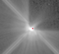
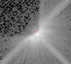
| Planned offset from center: -0.04" Planned SIAF pixel: 969.906; 698.626 POSTARG from BAR10: +17.45923 -7.53010 |
 |
 |
 |
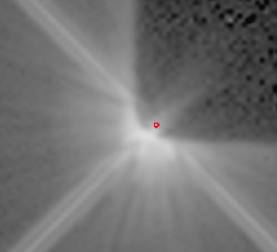
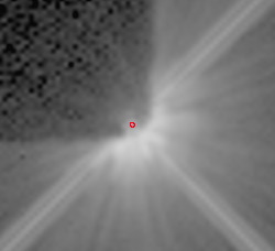
| Planned offset from center: 0.00" Planned SIAF pixel: 970.060; 699.400 POSTARG from BAR10: +17.46705 -7.49088 |
 |
 |
 |
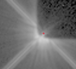
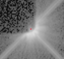
| Planned offset from center: 0.04" Planned SIAF pixel: 970.214; 700.174 POSTARG from BAR10: +17.47488 -7.45165 |
 |
 |
 |
| Planned offset from center: 0.08" Planned SIAF pixel: 970.369; 700.947 POSTARG from BAR10: +17.48270 -7.41242 |
 |
 |
 |
| Planned offset from corner: 0.15" Planned SIAF pixel: 600.217 819.404 POSTARG from BAR10: -1.28770 -1.40550 |
 |
 |
 |
| Planned offset from corner: 0.175" Planned SIAF pixel: 600.565 819.752 POSTARG from BAR10: -1.27002 -1.38782 |
 |
 |
 |
| Planned offset from corner: 0.2 Planned SIAF pixel: 600.914 820.101 POSTARG from BAR10: -1.25234 -1.37014 |
 |
 |
 |
| Planned offset from corner: 0.25 Planned SIAF pixel: 601.611 820.798 POSTARG from BAR10: -1.21699 -1.33479 |
 |
 |
 |
| Planned offset from corner: 0.3 Planned SIAF pixel: 602.308 821.495 POSTARG from BAR10: -1.18163 -1.29943 |
 |
 |
 |
| Planned offset from corner: 0.15" Planned SIAF pixel: 652.970 819.472 POSTARG from BAR10: +1.38744 -1.40205 |
 |
 |
 |
| Planned offset from corner: 0.175" Planned SIAF pixel: 652.622 819.820 POSTARG from BAR10: +1.36977 -1.38437 |
 |
 |
 |
| Planned offset from corner: 0.2 Planned SIAF pixel: 652.273 820.169 POSTARG from BAR10: +1.35209 -1.36669 |
 |
 |
 |
| Planned offset from corner: 0.25 Planned SIAF pixel: 651.576 820.866 POSTARG from BAR10: +1.31673 -1.33134 |
 |
 |
 |
| Planned offset from corner: 0.3 Planned SIAF pixel: 650.879 821.563 POSTARG from BAR10: +1.28138 -1.29598 |
 |
 |
 |
Beta Pic data
| Planned offset from center: -0.045" Planned SIAF pixel: 970.255 699.896 POSTARG from BAR10: 17.47699 -7.46566 |
 |
 |
 |
| Planned offset from center: -0.030" Planned SIAF pixel: 970.313 700.186 POSTARG from BAR10: 17.47993 -7.45095 |
 |
 |
 |
| Planned offset from center: -0.015" Planned SIAF pixel: 970.371 700.476 POSTARG from BAR10: 17.48286 -7.43624 |
 |
 |
 |
| Planned offset from center: 0.00" Planned SIAF pixel: 970.429 700.766 POSTARG from BAR10: 17.48579 -7.42153 |
 |
 |
 |
| Planned offset from center: 0.015" Planned SIAF pixel: 970.487 701.056 POSTARG from BAR10: 17.48873 -7.40682 |
 |
 |
 |
| Planned offset from center: 0.030" Planned SIAF pixel: 970.545 701.346 POSTARG from BAR10: 17.49166 -7.39211 |
 |
 |
 |
| Planned offset from center: 0.045" Planned SIAF pixel: 970.603 701.636 POSTARG from BAR10: 17.49460 -7.37740 |
 |
 |
 |
| Planned offset from corner: 0.225" Planned SIAF pixel: 601.301 821.377 POSTARG from BAR10: -1.23270 -1.30535 |
 |
 |
 |
| Planned offset from corner: 0.240" Planned SIAF pixel: 601.510 821.587 POSTARG from BAR10: -1.22209 -1.29474 |
 |
 |
 |
| Planned offset from corner: 0.255" Planned SIAF pixel: 601.720 821.796 POSTARG from BAR10: -1.21148 -1.28414 |
 |
 |
 |
| Planned offset from corner: 0.270" Planned SIAF pixel: 601.929 822.005 POSTARG from BAR10: -1.20088 -1.27353 |
 |
 |
 |
| Planned offset from corner: 0.285" Planned SIAF pixel: 602.138 822.214 POSTARG from BAR10: -1.19027 -1.26292 |
 |
 |
 |
| Planned offset from corner: 0.300" Planned SIAF pixel: 602.347 822.423 POSTARG from BAR10: -1.17966 -1.25232 |
 |
 |
 |
| Planned offset from corner: 0.225" Planned SIAF pixel: 651.996 821.480 POSTARG from BAR10: 1.33805 -1.30016 |
 |
 |
 |
| Planned offset from corner: 0.240" Planned SIAF pixel: 651.787 821.689 POSTARG from BAR10: 1.32744 -1.28955 |
 |
 |
 |
| Planned offset from corner: 0.255" Planned SIAF pixel: 651.578 821.898 POSTARG from BAR10: 1.31683 -1.27894 |
 |
 |
 |
| Planned offset from corner: 0.270" Planned SIAF pixel: 651.369 822.107 POSTARG from BAR10: 1.30623 -1.26834 |
 |
 |
 |
| Planned offset from corner: 0.285" Planned SIAF pixel: 651.160 822.316 POSTARG from BAR10: 1.29562 -1.25773 |
 |
 |
 |
| Planned offset from corner: 0.300" Planned SIAF pixel: 650.950 822.526 POSTARG from BAR10: 1.28501 -1.24712 |
 |
 |
 |
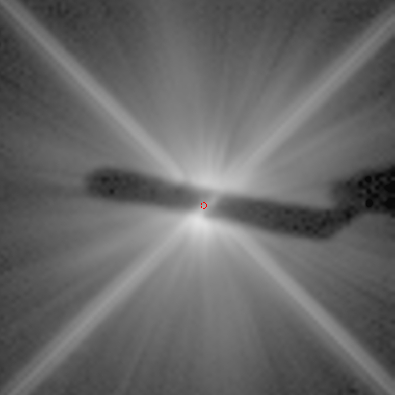
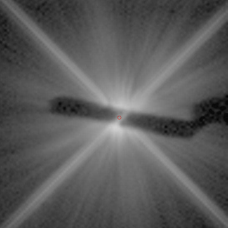
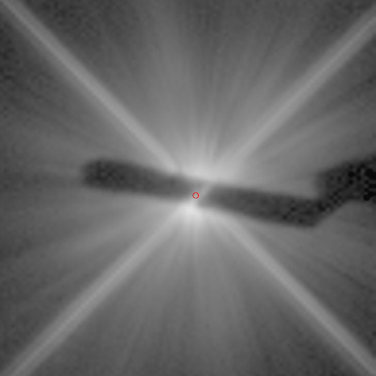
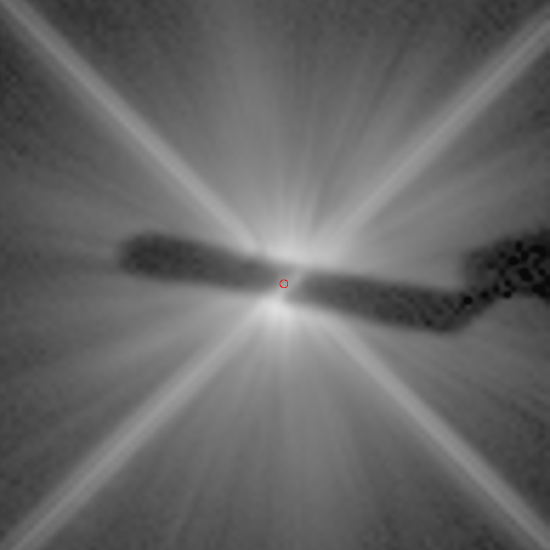
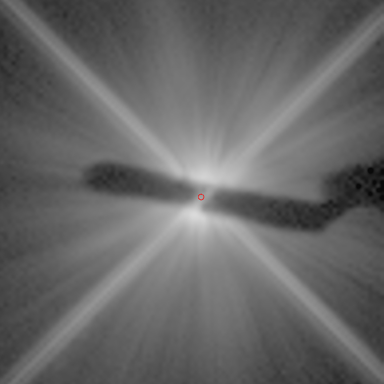
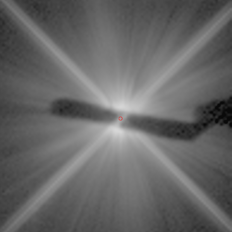
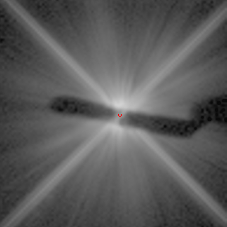
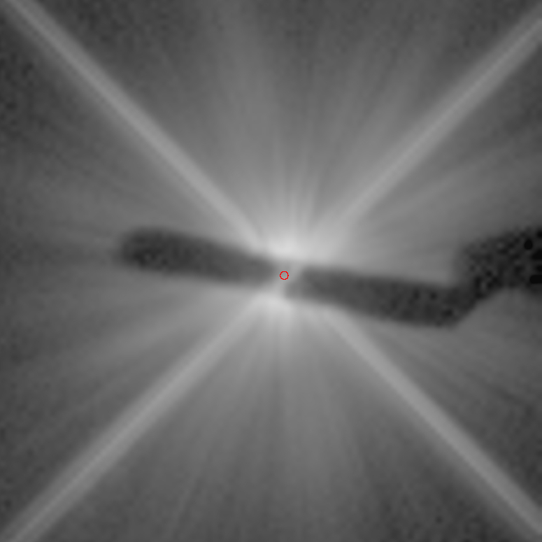
Locating the true position of an occulted star
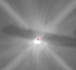
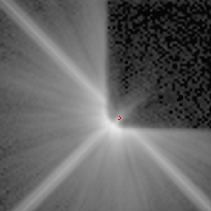
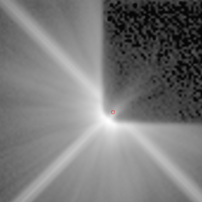
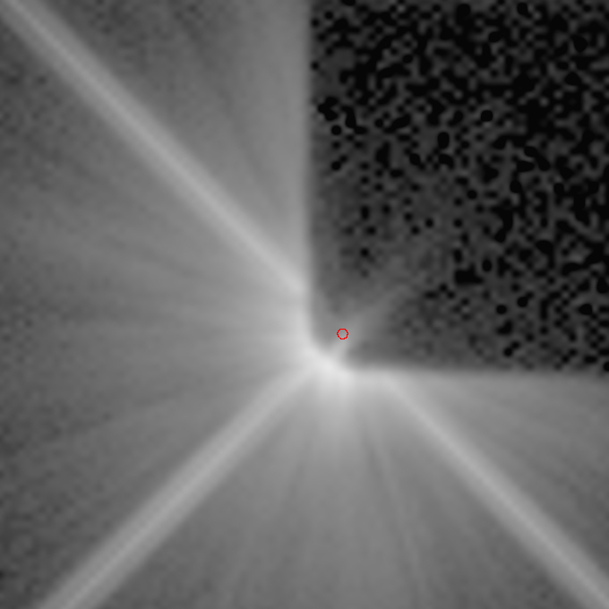
The location of the occulted (or partially occulted) star in each frame has been determined using the "X marks the spot" method that has previously been validated and used extensively in the GO program 12228. Simply, the photometric mid-lines (peaks intensity) along the nearly-orthogonal linear diffraction OTA spikes are found, fit, and the intersection computed. Over the few arcseconds of the region considered the (very small) effects of differential geometrical distortion are negligible. For the BAR5 aperture this is very straight forward, as the diffraction spikes are symmetrically seen in the four diagonal directions from the target. For the BAR10 coroner, one of the two spikes is nearly fully occulted on one side of the star by the mask itself - though peaks in the sub-array used for data readout on the side opposite the star and is used to better constrain the fit.
The method works, because the diffraction spikes (and origin at the true stellocenter) are unaffected by the introduction of the first focal plane image mask. Figure 6, for example, is a BAR10 image (left; obze06030) that was planned to have the stellocenter 0.2" interior to the BAR10 mask along a "45 degree" diagonal ([+2.76, -2.76] pixels in SIAF XY) tangent to the mask lower-left rounded corner (green dot, right panel). The "X marks the spot" solution reveals the star was not placed there, but was offset from that planned pointing by +0.068 -1.052 pixels (red dot). (The large Y direction offset is likely an artifact, due to the subarray readout and the subarray's starting Y index, which is believed to be at Center-Width/2, or 720-50=670 and 840-50=790, for the BAR5 and BAR10 images, respectively.)
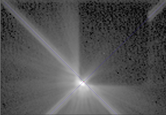
Figure 6: Locating a star with the "X-marks-the-spot" method.
The true stellar location (red dot), determined by the the "X marks the spot" method, vs. the planned location (green dot).